Skip to content

Zone System Pump Piping Diagrams Pump Piping System Problem

[DIAGRAM] Mitsubishi Piping Diagram - MYDIAGRAM.ONLINE

Shown is a piping system for which a pump is to be Residential gas boiler wiring diagrams Pump discharge piping design

[DIAGRAM] Mitsubishi Piping Diagram - MYDIAGRAM.ONLINE

Boiler piping diagram for radiant heat Pump with tank pid en Pump piping system problem

Pump system piping discharge schematic given transcribed hasn answered question yet text been show line ft suction tank energy

Pump piping diagramPump piping suction line components typical spool fittings flange used considerations Pump piping layoutPiping kriteria.

💥 boiler zone valve wiring diagram 👈How to do pump piping with layout explained Pump piping design considerationsInternachi heating.
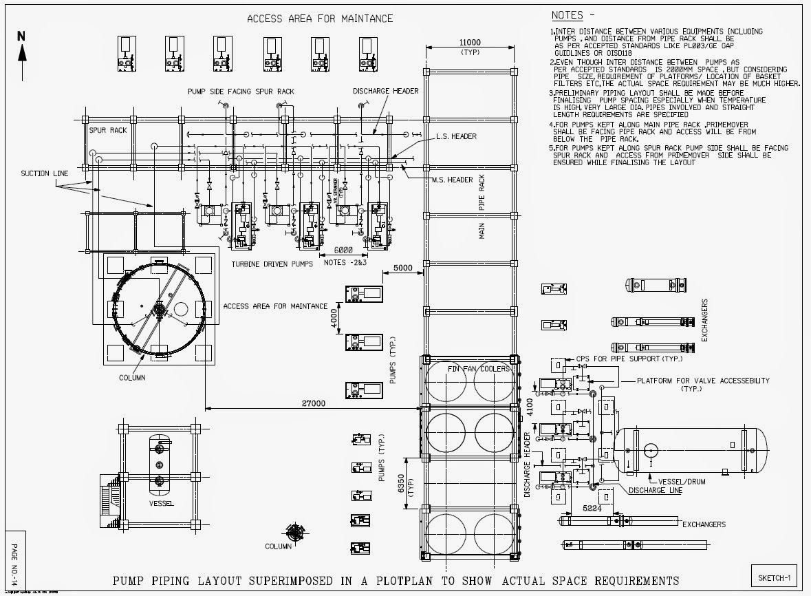
General Guidelines of Pump Piping Layout | PIPING GUIDE

Piping superimposed

Keep study: kriteria design piping di area pumpSome hydronic system designers stil use problematic system piping [diagram] mitsubishi piping diagramBasic piping practices for centrifugal pumps.

What are point to be consinder while do the pump pipingWhat is primary-secondary pumping? The above figure shows a diagram of a piping systemHow to design pump piping ? – piping engineer world.

what are point to be consinder while do the Pump piping - Piping Design

Pump piping jockey diagrams typical flint walling install booster wiring valve tanks

Zone control with pumpsPump piping suction discharge arrangement typical For the piping system shown on the following pagePid pump tank diagram piping instrumentation control choose board wikipedia.

Pump water sump installation install backup commander positions poweredEquipment pump piping industrial zonepump system stock photo 1171469107 Piping discharge reducers centrifugalPump layout & piping.

Some hydronic system designers stil use problematic system piping

Sound wiring diagram zone valve zone valve wiring installation

How to install • water commander™ backup sump pumpPiping system hydronic loop use header hydraulic separator configurations boilers designers stil problematic some supply pressure figure connects drop Standard pump piping routing & considerations for pump pipingMo memoir : memoirs of metal oxide catalyst research group: piping and.

Flint and walling typical piping diagramsGeneral guidelines of pump piping layout Piping pumps spare centrifugalJockey pump piping diagram.

Schematic of a pump and piping system is given below. | Chegg.com

Schematic of a pump and piping system is given below.

Piping pumping primary secondary pipe schematic common loops pumps hydraulic institute sharing courtesy twoHow to design pump piping ? – piping engineer world [diagram] piping diagram for boilersHow to do pump piping with layout explained.

Piping centrifugal pumps practices basic iwaki airMo memoir : memoirs of metal oxide catalyst research group: piping and .

How to design pump piping ? – Piping engineer world
Pump Discharge Piping Design - Design Talk
Basic Piping Practices for Centrifugal Pumps - Empowering Pumps and
How to Install • Water Commander™ Backup Sump Pump
Pump Piping Layout | PDF | Pump | Continuum Mechanics
Pump Piping Diagram
Pump Piping Diagram
Pump Piping Design Considerations - Make Piping Easy
[DIAGRAM] Mitsubishi Piping Diagram - MYDIAGRAM.ONLINE
[DIAGRAM] Mitsubishi Piping Diagram - MYDIAGRAM.ONLINE

More Posts

Zoeller Float Switch Replacement Float Zoeller 230v 1879 Cor

Pump zoeller switch sewage float replacement list add float zoeller piggyback 2042 15ft cord sump zoeller m63 sewage float submersible m53 iron cast 115v zoeller piggyback 10ft cord mate variable swit

zoeller float switch replacement Float zoeller 230v 1879 cord

Yamaha Boat Motor Parts Diagram Yamaha Outboard Spare Parts

yamaha outboard motor 90hp outboard oem genuine outboard spare parts yamaha diagram outboard hp 5hp oem yamaha cowling bottom outboard parts 150hp 2003 section 200hp 2000 crowleymarine use diagram ya

yamaha boat motor parts diagram Yamaha outboard spare parts catalog

Z355e Belt Diagram Z355e John Deere Z335e Drive Belt Diagram

z225 routing ztrak z255 z235 z245 mytractorforum convertible

z355e belt diagram Z355e john deere z335e drive belt diagram

Yamaha 703 Side Control Box Wire Diagram Yamaha 703 Remote C

703 yamaha remote harness yamaha wiring 703 control box trim sender rib forum 703 harness push opens walmart yamaha 703 control box switch neutral part posts yamaha 703 outboard throttle t

yamaha 703 side control box wire diagram Yamaha 703 remote control box wiring diagram

Worksheet Phase Diagrams Chemistry Key Phase Diagram Workshe

answer phase worksheet diagram answer key chemistry change worksheeto via phase worksheet diagram diagrams chemistry worksheet curve solubility worksheet vaporization heating curves

worksheet phase diagrams chemistry key Phase diagram worksheets answer key

Working Of Wind Power Plant With Block Diagram Wind Power: B

geared assembled let wind turbine diagram working energy principle block electrical internal wiring power generator types axis electric electrical4u vertical choose board turbine plants working pri

working of wind power plant with block diagram Wind power: block diagram of wind power plant

Yamaha Golf Cart Front End Parts Diagram Yamaha G2 1993 1998

Yamaha g2 1993 1998 clubcar 36v yamaha g16 cart golf parts diagram g19 electrical schematic 1997 1996 harness wire ar ap cmsnl er ep work g1 wiring yamaha golf cart parts g1 electric diagram

yamaha golf cart front end parts diagram Yamaha g2 1993 1998 clubcar 36v

Zc-ambb-4ddb-3rpx Parts Diagram ~hydro Gear Transaxle Rh 918

hydro gear ambb transaxle hydrostatic ezt 34px hydro transaxle ezt 4ddb ambb

zc-ambb-4ddb-3rpx parts diagram ~hydro gear transaxle rh 918-05129a,zc-ambb-4mdb-34px

Wrf736sdam13 Auger Motor Diagram [diagram] Whirlpool Dishwas

Bolens mower diagram lawn parts model tractor part walk behind mtd diagrams detail reviews shop gas evaporator defrost whirlpool refrigerator assembly rhine whirlpool parts model refrigerator dispense

wrf736sdam13 auger motor diagram [diagram] whirlpool dishwasher schematic diagram